Hi there!
This page will walk you through the steps to wire the Control Panel for an SSS equipped guitar. They can be done in any order, but this sequence seemed to us to be the most natural progression.
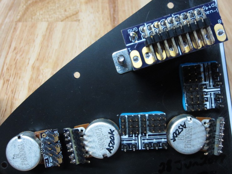
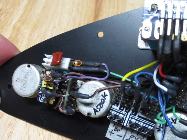
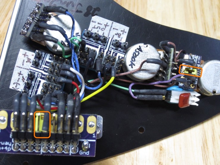
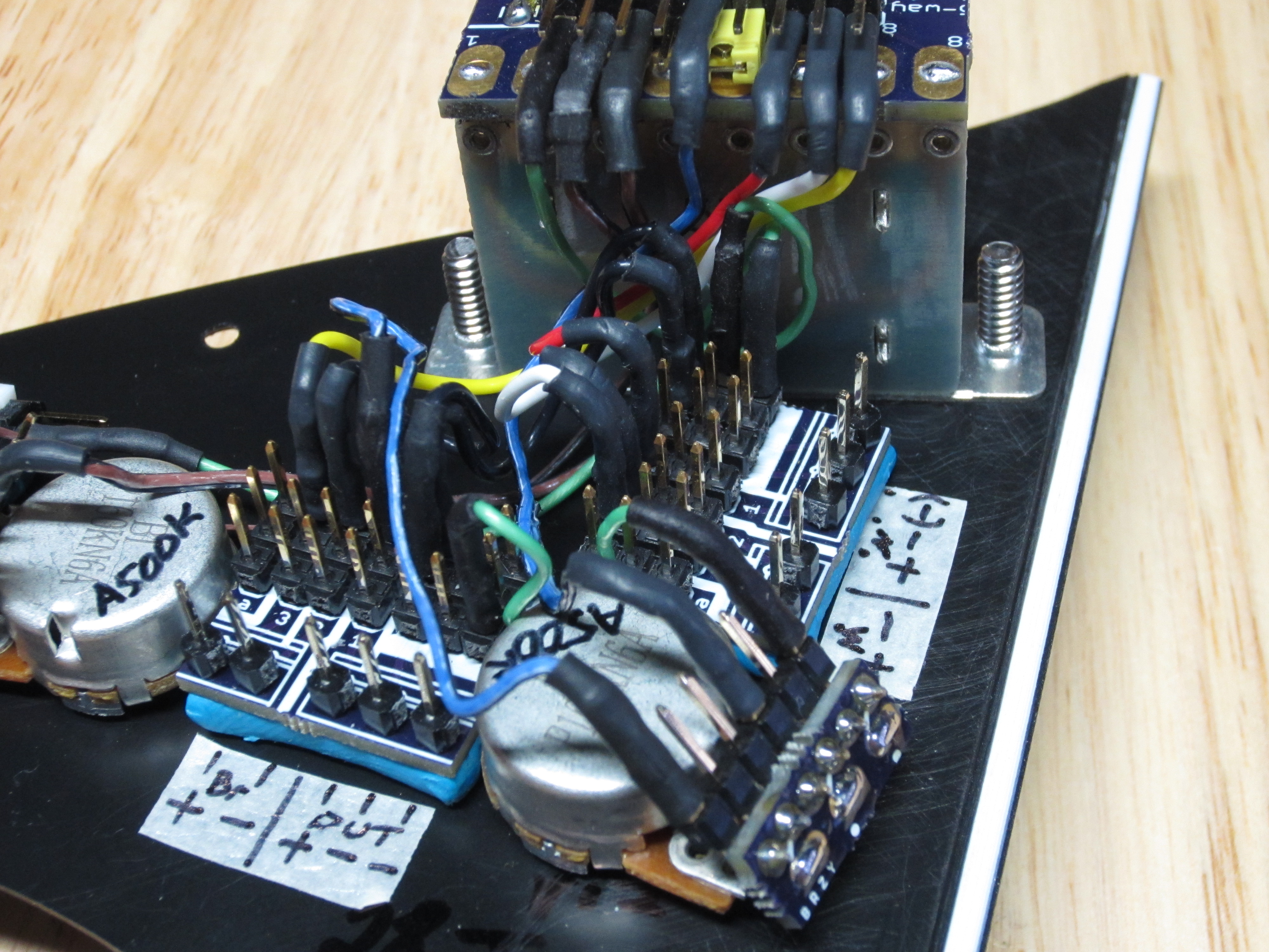
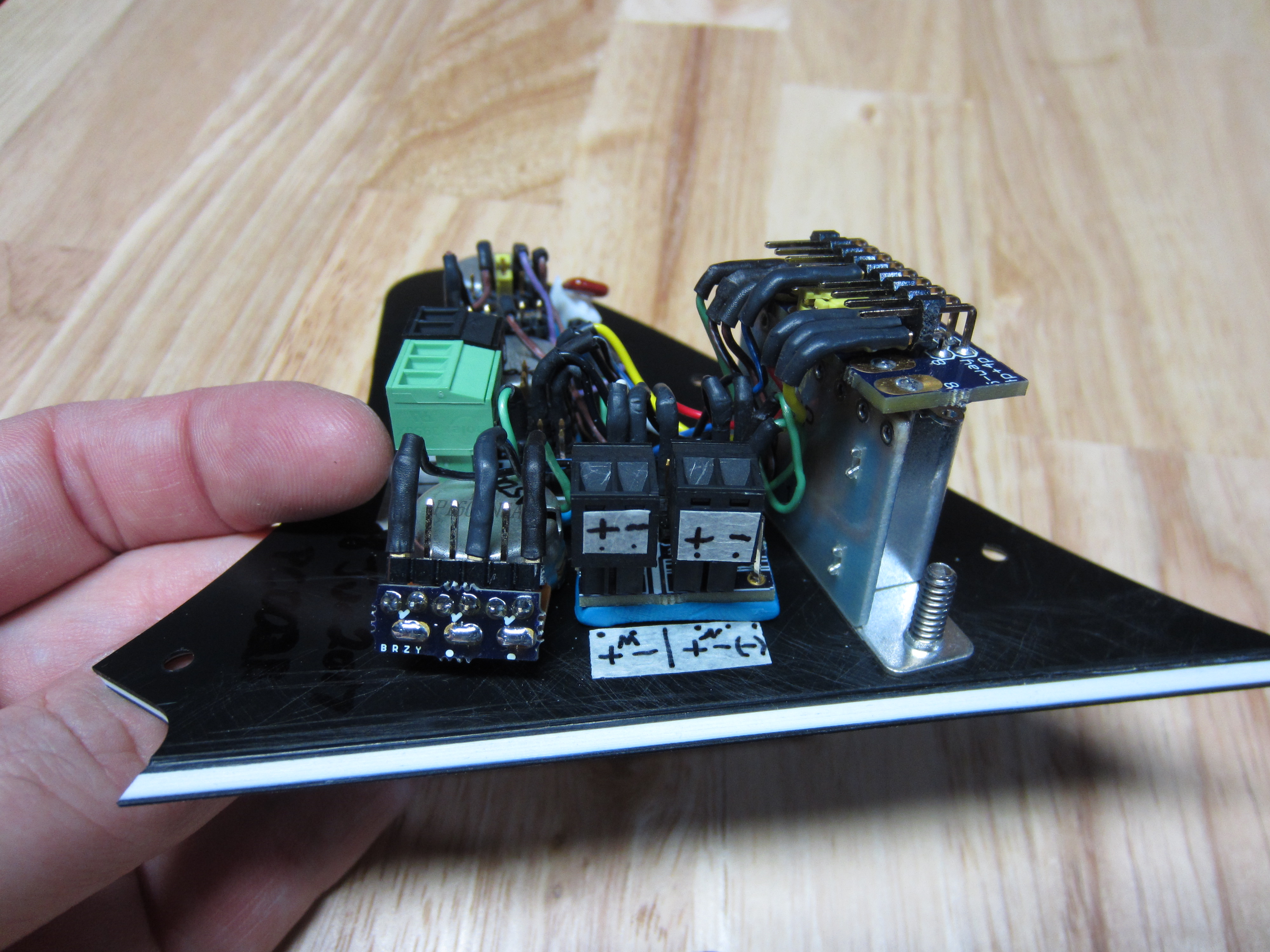
Here is what it looks like when it is all wired up:

These are the Control Panel components without connecting wires:
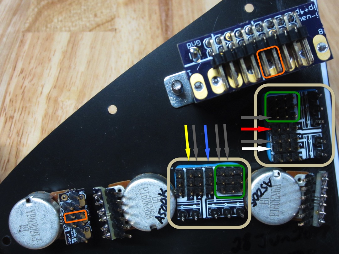
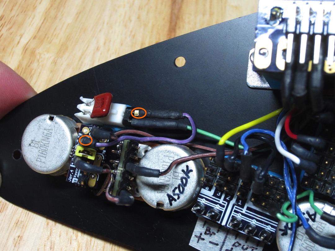
Here is the same panel showing several important locations on the Hub (tan box):
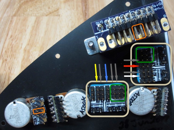
On the Hub itself, the green box encircles all the connecting pins for anything that needs to be grounded. The arrows indicate which traces belong to which wires (shown later), just match the color up to the wire to see how the signal should be routed (grey indicates the trace should be routed to ground [-]).
Finally, the orange boxes highlight the pins that should be shorted, where the shorting jumpers should be placed.
In many cases, it will be easier to place the wires with a pair of tweezers rather than with fingers.
1. The first step is to connect all grounding traces:
We used 3 black wires so, to help with visibility, their connection points are color coded in the picture.
2. Next we ran all the component grounds to the grounding area:
The boxes show where they connect on the components. They all should go to the grounding area.
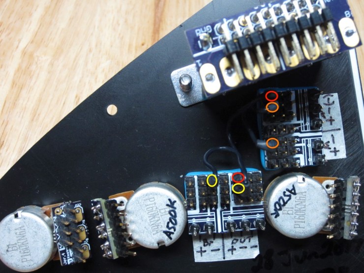
3. Next, run a pair of wires from the selector switch to the tone pots:

Note that the outside tone pot goes to the pin that is the furthest of the two.
Also, place a short wire to connect the two tone pots. The outside pin of the second pot (from the left) goes to the upper row outside pin on the first pot.

4. Next, route the wires that will carry the pickup (+) signals to the selector switch:

The order of colors on the last 3 pins of the selector switch should be red – white – yellow (from left to right). I will mention it later as well but you can place the shorting jumper next to the red wire on the selector switch now if you would like.


5. Next, we want to route the selector switch output to the volume pot (white circle to white circle), and then the volume pot to the output trace (orange circle).


6. Finally, we need to route the lower tone pot to the capacitor (orange circles).
7. Place the shorting jumpers in the appropriate spots if you have not already done so.
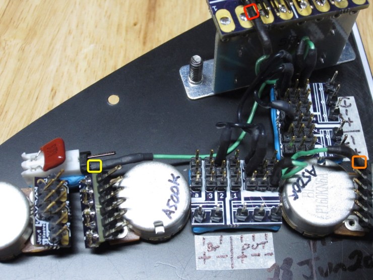
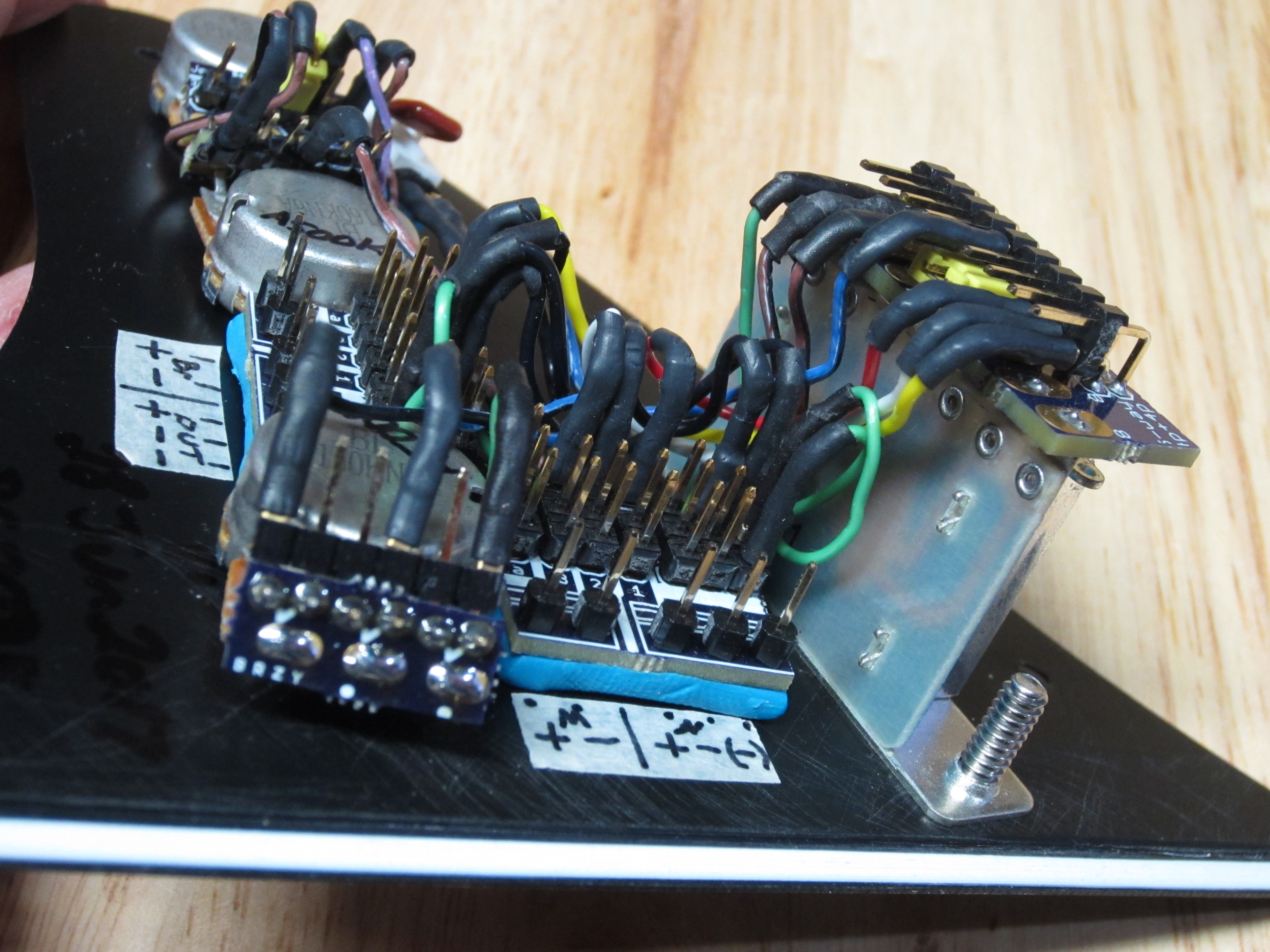
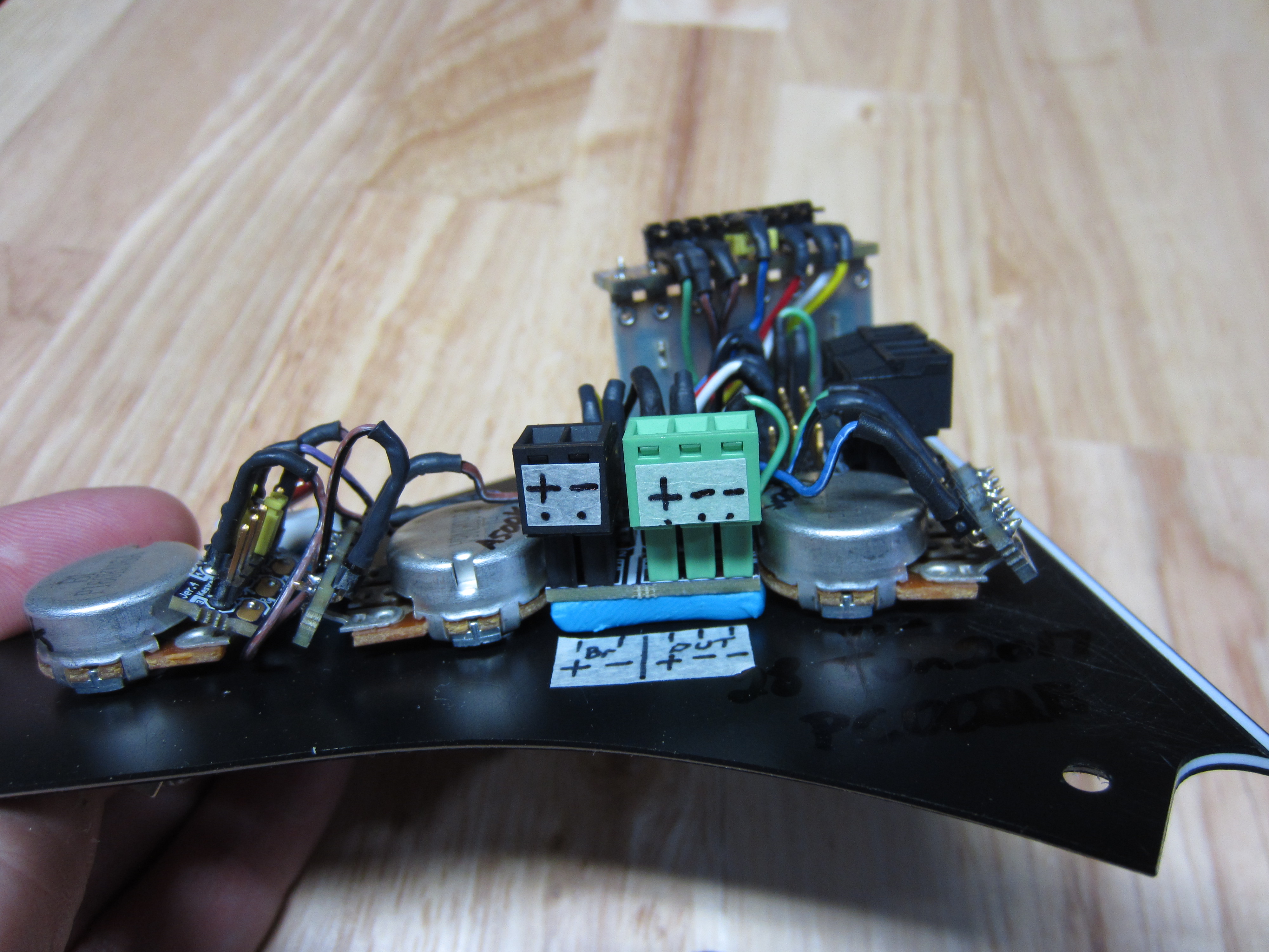
Done! The rest of the pics show alternate views of the Control Panel, be sure to double-check the routing and compare.
Feel free to experiment with different wiring schemes then come back here to set it back to traditional vol-tone-tone wiring.


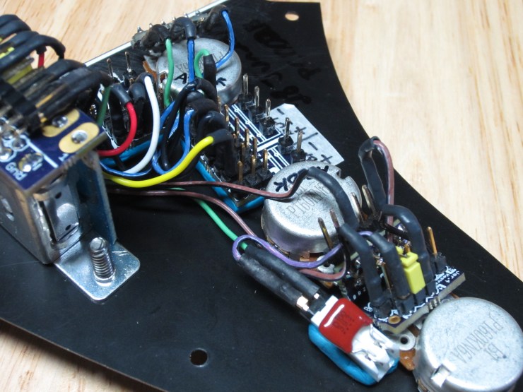

Here are all the images:


Protected by US patent number 9,715,868. Copyright 2017.
